

Someone just made a thread on here about doing this and I didn't want to link them to CF...So I figured I'd transfer my DIY to here, along with posting of the pin diagrams.
First off, You will need to remove your gauge cluster. To do this, you have to remove the two screws located on the black plastic piece of trim around the cluster.
If this is your first time removing the cluster bezel, you will need to get a butterknife or something that's less likely to damage the plastic, and slide it along the bottom edge. It's glued on there. It will put up a little fight, but just take your time and you'll be okay.
Then to remove the actual cluster, take the 3 screws off (2 on bottom, 1 on top) and tilt the top of it forward so you can unplug the connectors. Wiggle the cluster out of the dash and put that ugly MoFo on eBay!:domo:
Before it was installed, after it got cleaned up really nice
![Image]()
Got it installed finally...here's the finished product
![Image]()
This is going to be a long read of some tips and tricks and issues I had that might come in handy for anybody doing this in the future...
1. The Wiring
Once I figured out the trick, I had the green cluster de-pinned in 5 minutes, not exaggerating one bit. I know it's supposed to be easy to figure it out, but to someone like me who's never done this type of thing before, it was tricky to figure out. Just trying to help all the newbs out")
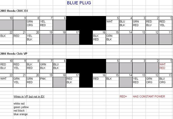
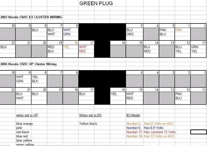
The pin-swapping: Only thing I noticed that was a bit convuluded was on DirtySamurai's wiring guide (Thread link HERE), the white-red wire that goes into the green connector listed both as going into the same pin slot. From looking at the diagram , I went with the white-red wire from the blue cluster and moved it over to the green one. Just FYI. Also, the red-white wire from the green cluster was the only wire I didn't use. . Like it's been said before, the only wire needing to be extended was the Yellow-Black wire being taken from the green connector to the blue connector. I just cut, spliced using butt connectors, and taped over the connectors just to be safe. The only wire I needed that was listed that I didn't have was the green-black wire in the blue connector. Everything works fine so I'm going to assume it's either DRL or Side SRS. Both of which my car doesn't have.
How I removed the pins (Complete idiot's guide)
I used a paperclip, about maybe 2 millimeters in diameter, to get the pins out. I used my Dremel and grinding stone to sharpen the end as to slide in easier and to decrease diameter a bit. I also put an upwards bend on the sharpened end to make it easier to wedge in there. First visual aid:
![Image]()
This is the way you get the pins out. Quick note - Looking back on it I suppose you could go in the bottom hole if you really wanted to, but going in from the top helps you you avoid the tab at the end of the pin and also sets up a good angle to help unlock. This is the way I did it, and I can definitely vouch for it.
For each top and bottom row, there are two holes for each pin. You want to go in from the top hole, and angle down towards the bottom hole. This is where the upward bend on the paperclip comes in handy. If you angle too soon, you'll hit a little tab on the floor of the pin. It takes a bit of time to get where to wedge it in, play around with it. Optimally, this is the angle you want to get on it:
![Image]()
Next step: Once you find the spot, you'll feel it get tougher to slide in, and then it'll stop (You've just hit the spot where the wire is crimped at on the connector... It's a good thing!) While holding the paperclip in place, give the wire a little tug. It should move out a little bit. Now remove the paperclip, and it should slide out no problem. I found if you try to leave the paperclip in, you run a higher chance of taking the wire out instead of the actual pin (Found out the hard way)The only wires that didn't slide out easily were the ones I had screwed with the last time I tried to do this.
2. Cluster issues
So anyways, on to the issues. I had noticed when I got it that the gas/temp needles were out of place, as if they had did a full rotation. I had rotated them by hand to where I thought they should be, but when I turned the car on the temp needle went flying into the gas needle and got stuck. So I took it out and played with it a bit, rotating it Clockwise and Counterclockwise....When I rotated it CW, it went to the starting point fine. Rotating CCW, it was stopped from rotating any further right at operating temp. After taking the cover off and playing with the needles around 5 times, I finally decided to move the Temp needle CCW to the starting point. I had to go against the little motor in there. It clicked while I was doing it, but I did it quite carefully, not wanting to break anything. Started the car up and let it idle...and to my surprised, worked like a charm. Ended up having to turn the gas needle CW to the starting point as well. Both are working fine now, so if anybody gets a cluster and notices this problem, there's your solution
And here are the pin diagrams that I have, for reference.
![Image]()
![Image]()
Here's an alternate version...
![Image]()
All you have to do is swap the wires from pin location to location, and in a couple cases from green connector to blue connector. IIRC you have to extend 1 wire. Also, if you have left over wires, don't freak out. Just double check everything is right...and if it's not needed, then just cap it and don't worry about it.
First off, You will need to remove your gauge cluster. To do this, you have to remove the two screws located on the black plastic piece of trim around the cluster.
If this is your first time removing the cluster bezel, you will need to get a butterknife or something that's less likely to damage the plastic, and slide it along the bottom edge. It's glued on there. It will put up a little fight, but just take your time and you'll be okay.
Then to remove the actual cluster, take the 3 screws off (2 on bottom, 1 on top) and tilt the top of it forward so you can unplug the connectors. Wiggle the cluster out of the dash and put that ugly MoFo on eBay!:domo:
HOW TO REMOVE PINS FROM CONNECTOR
http://videos.streetfire.net/video/dcf2362e-2fdb-493d-84fd-990a014958b4.htmBefore it was installed, after it got cleaned up really nice

Got it installed finally...here's the finished product

This is going to be a long read of some tips and tricks and issues I had that might come in handy for anybody doing this in the future...
1. The Wiring
Once I figured out the trick, I had the green cluster de-pinned in 5 minutes, not exaggerating one bit. I know it's supposed to be easy to figure it out, but to someone like me who's never done this type of thing before, it was tricky to figure out. Just trying to help all the newbs out
The pin-swapping: Only thing I noticed that was a bit convuluded was on DirtySamurai's wiring guide (Thread link HERE), the white-red wire that goes into the green connector listed both as going into the same pin slot. From looking at the diagram , I went with the white-red wire from the blue cluster and moved it over to the green one. Just FYI. Also, the red-white wire from the green cluster was the only wire I didn't use. . Like it's been said before, the only wire needing to be extended was the Yellow-Black wire being taken from the green connector to the blue connector. I just cut, spliced using butt connectors, and taped over the connectors just to be safe. The only wire I needed that was listed that I didn't have was the green-black wire in the blue connector. Everything works fine so I'm going to assume it's either DRL or Side SRS. Both of which my car doesn't have.
How I removed the pins (Complete idiot's guide
)I used a paperclip, about maybe 2 millimeters in diameter, to get the pins out. I used my Dremel and grinding stone to sharpen the end as to slide in easier and to decrease diameter a bit. I also put an upwards bend on the sharpened end to make it easier to wedge in there. First visual aid:

This is the way you get the pins out. Quick note - Looking back on it I suppose you could go in the bottom hole if you really wanted to, but going in from the top helps you you avoid the tab at the end of the pin and also sets up a good angle to help unlock. This is the way I did it, and I can definitely vouch for it.
For each top and bottom row, there are two holes for each pin. You want to go in from the top hole, and angle down towards the bottom hole. This is where the upward bend on the paperclip comes in handy. If you angle too soon, you'll hit a little tab on the floor of the pin. It takes a bit of time to get where to wedge it in, play around with it. Optimally, this is the angle you want to get on it:

Next step: Once you find the spot, you'll feel it get tougher to slide in, and then it'll stop (You've just hit the spot where the wire is crimped at on the connector... It's a good thing!) While holding the paperclip in place, give the wire a little tug. It should move out a little bit. Now remove the paperclip, and it should slide out no problem. I found if you try to leave the paperclip in, you run a higher chance of taking the wire out instead of the actual pin (Found out the hard way
)The only wires that didn't slide out easily were the ones I had screwed with the last time I tried to do this. 2. Cluster issues
So anyways, on to the issues. I had noticed when I got it that the gas/temp needles were out of place, as if they had did a full rotation. I had rotated them by hand to where I thought they should be, but when I turned the car on the temp needle went flying into the gas needle and got stuck. So I took it out and played with it a bit, rotating it Clockwise and Counterclockwise....When I rotated it CW, it went to the starting point fine. Rotating CCW, it was stopped from rotating any further right at operating temp. After taking the cover off and playing with the needles around 5 times, I finally decided to move the Temp needle CCW to the starting point. I had to go against the little motor in there. It clicked while I was doing it, but I did it quite carefully, not wanting to break anything. Started the car up and let it idle...and to my surprised, worked like a charm. Ended up having to turn the gas needle CW to the starting point as well. Both are working fine now, so if anybody gets a cluster and notices this problem, there's your solution
And here are the pin diagrams that I have, for reference.
Here's an alternate version...

All you have to do is swap the wires from pin location to location, and in a couple cases from green connector to blue connector. IIRC you have to extend 1 wire. Also, if you have left over wires, don't freak out. Just double check everything is right...and if it's not needed, then just cap it and don't worry about it.


